miceeestudents

Showing posts with label TECHNICAL ARTICLES(session-2). Show all posts


INTRODUCTION

    Renewable energies are those forms of energy that derives from the natural movements and mechanisms of the environment – sunshine wind, the heat of the earth, the growth of plants and animals, the movement of the seas and rivers.  They are classified into 1) Solar Energy, 2)Bio-mass Energy, 3) Hydro Energy, 4) Wind Energy, 5) Ocean Energy, 6) Geothermal Energy.

Among these SOLAR Energy has the distinctive features that are clean, environment friendly, inexhaustible and readily available energy everywhere and so on.  The density of solar energy is low but it is suitable for a distributed utilization.  More conventional forms of energy, the fossil fuels.  Recovered their Solar energy input eons ago and possess the energy in a greatly concentrated form.
Applications of Solar Energy

1)    Solar water heating, air heating,  Solar cokkers.
2)    Solar engines for water – pumping.
3)    Photo voltaic conversion.
4)    Solar fumaces, Solar thermal power generation.
SOLAR TRACKERS

    Solar tracker is a PV array support structure following the sun during the day.   As a result of the movement, the modules face the sun directly the whole day thus give much more electricity compared with fix mount modules.  The original TRAXLE tracker was purpose developed and patented on most of the world markets.  

Function of the Sun Tracker
    The sun tracker is an apparatus which can follow the sun’s track from its rising in the east to its setting in the west.  The TRAXLE solar tracker is an assembly consisting of aluminum profiles and stainless steel.  Photovoltaic panels are attached to this assembly.  Because the solar tracker turns after the sun, the photovoltaic panels face the sun directly all day long and their performance is thus substantially enhanced.
Technical Solution

    The technical solution of the TRAXLE tracker is unique, with two patents issued, valid worldwide.  The main load bearing part of TRAXLE is an aluminium or stainless stell pipel oriented slantwise on the north/south axis.  Arms with photovoltaic panels are attached to the pipe.  The pipe has a built in DC motor with tunrs the entire assembly with a worm gear unit.  The motor is powered by PV module attached to the bottom part of the pipe.  The module is mounted perpendicularly toward the sun and contains PV cells on both sides.  The TRAXLE sun tracker to that side of the small PV module which is exposed to the sun.


Advantages of TRAXLE
•    enhances performance of photovoltaic modules by 30%
•    enhances performance of water pumps by 70%
•    robust construction from stainless steel and aluminium profiles
•    easy installation, unattended operation
•    no maintenance of the assembly required
•    works even in winter
•    self-locking gear protects against gusty winds
THE TRACKER

    At least one solar cell is fixed to rotary axle of the tracker and its plane is declined, from the plane parallel to the axle and perpendicular to the collectors of solar energy, approximately by 20o eastwards.  The solar cell is connected directly to a DC electromotor.  Both the motor and the self-locking transmission are integrated in the tracker axle.

    Figures show principle of the tracker.  Solar collectors are oriented eastwards.  As the sun moves from the east to the west, angle of incidence  of solar radiation of sensing / driving cells increases until power of the driving DC motor, connected to these cells, is high enough to move solar collectors.  Then the angle of incidence  starts to decrease until the power of the DC motor is lower than the necessary to move solar collectors.  Additional antiparallel solar cells, placed in the same panel, enables back tracking of the tracker from any position.


Integration of antiparallel solar cells in one “bifacial” panel makes the tracker more compact, more reliable and less expensive.  Antiparallel solar cells can be even manufactured monilitically on single substrate.  Backtracking time of the new tracker is a few minutes only even in cold climate while by passive trackers the backtracking time is more than one hour at the same temperature.

    The efficiency of the tracker increases with efficiency of solar panels.  Force necessary to overcome friction and aerodynamic drag remains constant while the area related output power of driving / sensing solar panel increases.


SPECIFICATION
General description: Single axis solar tracker based on antiparallel “bifacial” driving/sensing solar panels connected directly to the reversible DC motor.
Weight of tracker     Max. 8 kg/m2
Standard size    1-25m2   
Length of the TRAXLE TM    2-8M
Weight of Collectors    Max. 15 kg/m2
Tracking accuracy    100
Backlash    <20
Tracking angle    1200
Max. static torque    500 Nm
Area related torque    2 Nm/m2
Max. windspeed    140 km/h
Backtracking time    5 min.
Temperature range    -30 + 800c
Water & dust protection    IP67

Main advantages of the new tracker over other systems
•    Works also at low temperature down to –300c
•    Collectible energy surplus up to 40% over fixed arrays.
•    Pumping capacity surplus up to 80%
BIFACIAL SOLAR PV MODULES
    Bifacial PV modules are modules utilizing the sunshine from both the “front face” and the “back face”  of the module.  The use of the reflected light from the back side gives bifacial modules the advantage against standard PV monofacial modules.  Bifacial modules simply collect more light and give more power.  When installed on a TRAXLE solar tracker, the PV energy gain can be up to 50%.
    Because there is either no or low price difference in the price of such bifacial and monofacial modules it is reasonable to use bifacial modles which could produce 5-20% more energy.  Additionally solar trackers/ concentrators are usually oriented to the west, before backtracking in the morning. The bifacial modules enable to collect direct back side solar radiation before backtracking.  According to local climate the resulting energy gain coul be 2-5%.
It is also very advantageous that bifacial PV modules transparent for infrared radiation, has lower operating temperature against monofacial ones.  It is especially advantageous by solar trackers and tracking soft concentrators where PV modules are exposed to higher solar radiation than on fixed racks.  As indicated above solar trackers/concentrators are always mounted on high support structures which improve cooling of PV modules by air flow.  The reduced


temperature is also very important for lifetime of PV modules in soft concentrators.  It should help to avoid degradation of polymer encapsulants of modules cased by higher temperatures of monofacial modules.  The new bifacial PV modules with reduced temperature sensitivity can further increase the system energy gain by up 10%.  The polar axis solar tracker with c-Si bifacial PV modules will therefore deliver by about 50% more energy than fixed c-Si monofacial PV array with the same rated output power.

Concentrator

    In the PV industry, a concentrator is a mirror that reflects additional sun shine to the PV modules.  By this, the modules get more light and produce more electricity.  The concentrators can be produced from various materials such as stainless steel, aluminum alloys, silver coated polymers or silver coated hardened glass.

Why track the sun?

    The power generated by a PV panel is directly related to the amount of light it intercepts.  More light = more power; its as simple as that.
The threeidentical PV panels at left are oriented in different directions relative to the sun’s rays.  Panel “A”, faces the sun directly and its large shadow shows that it intercepts the maximum possible solar energy.  Panel “B” does not face the sun, but is diagonal to the sun’s rays.  It smaller shadow shows that panel “B” intercepts much less energy than “A”.  Finally, panel “C” is aimed perpendicular to the sun’s rays and its tiny shadow shows that it intercepts very little of the available energy.


Pump 50% more water with a Sun Tracker 8!

Solar pumping systems which use a Sun Tracker 8 to keep their PV panels aimed at the sun can produce 50% more water than pumping systems using stationary PV panels.  The Sun Tracker 8 allows the pump to turn on earlier and stay on later – this means more hours of pumping and produced by the very low light levels of dusk and dawn, we have developed a system which will return east in time to catch the early morning sun – without batteries!  As a result, we no longer include internal batteries with our systems.  This new feature is especially useful in well pumping applications where pumps are connected directly to PV panels and batteries are not needed or desired.

More Light  = More Power

    The amount of power produced by a photovoltaic panel depends upon the amount of sunlight it is exposed to.  More light means more power.  To intercept the most sunlight, a photovoltaic panel must be positioned so that the sun’s rays arrive at the panel directly; perpendicular to its surface.  When a photovoltaic panel is not aimed directly at the sun, it does not intercept as much light as it can.  And consequently, it does not produce as much power as it can.


Fixed vs. Tracking

    Because of the earth’s constant motion, fixed (unmoving) photovoltaic panels rarely (if ever) aim directly at the sun.  consequently, fixed panels intercept far less sunlight than they can.  And as a result, they produce much less power than they are capable of producing.  Photovoltaic panels mounted on a Sun Tracker 8 solar tracker, on the other hand, are always aimed directly at the sun from sunrise to sunset.  As the sun’s position changes throughout the day, the Sun Tracker 8 continually adjusts the orientation of the panels so they are always aimed precisely at the sun.  And as a result, photovoltaic panels on a Sun Tracker 8 collect the maximum amount of sunlight and  product the most power possible.

The Sun Tracker 8
    Sun Tracker 8 is a pole mounted electronic solar tracking system which needs no battery.  Our weatherproof solid-state tracking electronics sense the sun’s position and control one or two heavy-duty actuator motors which keep the array aimed directly at the sun.  at nightfall, Sun Tracker 8 turns the array east so that it is ready for the first rays of the next sunrise.
Consumes Very Little Power

    Sun Tracker 8 is designed to consume very little power.  Because the apparent motion of the sun across the sky is very slow, the Sun Tracker 8’s motion must also be very slow.  Consequently, the periodic position adjustments made by Sun Tracker 8’s motor(s) normally last only a fraction of a second.  As a result, total daily power consumption is  very small.  The solid – state tracking electronics themselves draw maximum of 7.5mA at 12V for a total of .15W or 3.6 watt hours per day.  Consider that in just one hour a 25-watt light bulb uses 7 times the power that the Sun Tracker 8’s tracking electronics use
Durable and Reliable
    Sun Tracker 8 is durable and reliable.  Unlike passive tracking systems that use environmentally harmful Freon, the Sun Tracker 8’s performance is not adversely affected by cold temperatures or wind.  The system’s heavy-duty linear actuators lock firmly on target, even in the iciest of winter gales.  The Sun Tracker 8 is designed to withstand winds in excess of 100 mph and to operate in temperatures from –40F to 140 F.  American Sun co backs every Sun Tracker 8 with a limited 10-year warranty.

Easy Installation
    The Sun Tracker 8 is designed for quick, easy installation.  In most cases, one person can install a Sun Tracker 8 in les than four hours.  And because Sun Tracker 8 has full adjustable mounting points, almost any type of photovoltaic panel can be accommodated.  Once the Sun Tracker 8 has been set up, there is virtually no maintenance.

Very Economical
    The Sun Tracker 8 is economical.  By keeping your array aimed directly at the sun, all day, every day, the Sun Tracker 8 makes the most of your photovoltaic investment.  With a Sun Tracker 8, you get substantially more power from each PV panel in your array.  And this increase in power results in a lower cost per watt and a shorter payback period for your entire system.

CONCLUSION

So, Solar tracking place a prominent role in production of electricity as:
•    It can  withstand winds in excess of 100 mph
•    Operate in ambient temperature between –400F and 1400F.
•    Turn east at night in preparation for the next day’s sunrise.
•    Aim at the brightest area of the sky during overcast conditions.
•    Limit “sun during partly cloudy conditions.

REFERENCES

1.    ASME journal of Mechanical Engineering.
2.    Solar Energy by SP Sukhatme.
     URLs visited
www.solar-trackers.com.
       B.V.RAMARAO
                                                            10H71A0256
Read More …


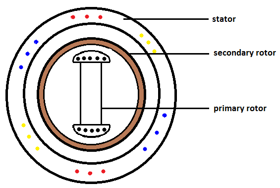
Till now we know about an AC Motor with only one rotor, but this is a special motor which has 2 rotors. The 2 rotors are primary and secondary.  Here the two rotors are coaxial but one inside the other that is the primary rotor will be inside the secondary.Construction:
The stator of this motor is similar to the stator of general 3 phase AC motor.  This motor contains 2 different types of rotors; primary rotor is a salient pole rotor and the secondary is hallow cylindrical rotor. These rotors have sliprings.

Working:
This motor can be operated in 3 different ways . They are

  1. Primary as synchronous motor and blocked secondary
  2. Both primary and secondary as synchronous motors
  3. Primary as synchronous motor and Secondary synchronous condenser

PRIMARY AS SYNCHRONOUS MOTOR WITH BLOKED SECONDARY:
As mentioned in this mode the secondary rotor is blocked and DC supply is given to the primary rotor. The 10 rotor also contains damper windings.  When 3-phase supply is given to the stator windings a rotating magnetic field is generated. By the faraday’s law of electro magnetism emf is induced in the damper windings. As the damper windings are short circuited current flows through it and the rotor starts rotating with a speed near to synchronous speed. Because of magnetic locking between the rotor and stator magnetic field 10 rotor will rotate with synchronous speed.
As the 20 rotor is blocked and the windings of this rotor are in rotating magnetic filed emf is induced in these windings also. By connecting a load to the sliprings electrical energy can be taken out. There will small phase difference between the stator emf and the 20 rotor but the frequency of induced emf will be same.
Hence the magnetic locking will be strong and effect of hunting can be suppressed more when compared with normal synchronous motor, even there is sudden change in loads.
Advantages:
  1. It draws less amount of current from the supply.
  2. Hunting effect can be reduced.
  3. Less variation in speed for sudden change in loads


Both primary and secondary as synchronous motor:
Here both 10 and 20 rotor windings are given dc supply. As mentioned above the 10 rotor will rotate but secondary rotor will not rotate so it must be stated as the induction motor. After reaching near to synchronous speed DC supply is given to the rotor. Then magnetic locking takes place and the rotor rotates with synchronous speed.

Primary as synchronous motor and Secondary synchronous condenser:
Here also dc supply is given to both the rotors but primary rotor is loaded and the secondary is not loaded. As the synchronous motor running under no-load  condition act as synchronous condenser we can use this machine as both synchronous motor as well as synchronous condenser at a time itself.
ADVANTAGES OF DUAL ROTOR SYNCHRONOUS MACHINE:
  1. It utilises less power.
  2. Hunting is suppressed well when compared with normal synchronous machine.
  3. It can be used as synchronous condenser as well as motor.
  4. By blocking secondary rotor we can take the electric supply and can be given to loads.
  5. Cheaper when compared with two separate synchronous motors.
  6. Same as normal synchronous motor this machine can also be used at various power factors
  7. By blocking secondary rotor and by short circuiting the windings of primary rotor we can use it as Induction machine.
DISADVANTAGE:
  1. It occupies more space than normal synchronous machine


By
K. Vinod Krishna
10H71A0259

Read More …

The majority of us accept as fact that the current administration manipulates science for political ends. Few were surprised to hear experts from industry challenge overwhelming evidence of man-made climate change. Frustration within the scientific community had grown so much that by Dec. 2006 more than 10,000 scientists, including 52 Nobel laureates and 63 recipients of the National Medal of Science, had signed a statement accusing the Bush administration of "distortion of scientific knowledge for partisan political ends".
Scientific integrity within the administration has often not been rewarded. Recently fired US surgeon general Richard Carmona said after leaving, "In public health, as in a democracy, there is nothing worse than ignoring science, or marginalizing the voice of science for reasons driven by changing political winds."
Truth, even when grounded in strong scientific evidence, is the first casualty of war, and the US is at war.

The pattern is clear, and it affects us all.


The only explanation supported by the physics is multiple explosions in both Towers. Without an additional energy source to blow the lower floor support structure out of the way of the falling upper mass, the observed fall speeds were unachievable. Any true scientific model must take into account the fact that that the kinetic energy of falling material would continually be dissipated to break more structural energy of parts of the remaining building unless explosions have already done the job. Thus, without explosions this mandatory expenditure would continually decrease the fall velocity through all the levels. In other words,
the top portions of the buildings as they came down would be significantly Even if the fires had gutted the entire building, causing universal structural weakening, the fall times would still be about 2-3 times longer than the fall time observed. In reality, the North Tower had 92 floors and the South Tower had 77 floors of intact structure designed to withstand major adverse damage below the impact zone and fires. If the planes and fires did more minor damage to the buildings before setting off the supposed critical fall, either building would take
3-10 times as long for complete collapse than was observed, even if complete collapse could occur and even then if it occurred all at once. slowed down by the undamaged parts of the buildings below.

Is there proof of how the buildings came down? Examining the more technical details of the collapse shows direct evidence that explosives caused the collapse. Videos and photos taken clearly show the very-quick appearance of rapidly growing dust clouds in the collapse of the both Towers. These clouds expanded much faster than the gravitational pull could produce, clearly indicating that explosive heat energy caused that expansion. Multiple squibs (material ejecting horizontally from high-pressure regions) traveling over 160 feet a second were observed in both towers, and could only be generated by explosions. Several parallel squibs came out of the South Tower just a floor or 2 below where the plane hit less than an hour before, and these explosions that caused the twisting of the top 34 floors that initiated the collapse of that tower. Multiple squibs were also seen at the times of collapse of building 7, which collapsed later that day and was not hit by any plane. The appearance of these squibs in all 3 cases came within seconds of the time each building started to collapse.

Defenders of the NIST Reports have tried use to explain these squibs as compressed air and gasses coming out of the collapsing buildings, but that cannot begin to account for the energetic focused horizontal blasts observed. Explosions produced those extremely high speeds, making the ejecting material into a swath of bullets shooting out of the buildings.
                                                                                                            B.v .ramarao
                                                                                                             10H71AO256
Read More …


As an electrical student we MUST know all the measures that has to be taken in the work place. A safe work environment is not always enough to control all potential electrical hazards. We must be very cautious and work safely. Safety rules help you control your and other risks of injury or death from work place hazards.
If you are working on electrical circuits or with electric tools and equipment, you need to use the following rules:
1. Avoid contact with energized electrical circuits. Please don’t make fun of this rule if you already know this (and you probably already know if you are reading these lines) and remember that if something bad occurs-you probably won’t have other chance. That’s not funny.
2. Treat all electrical devices as if they are live or energized. You never know.
3. Disconnect the power source before servicing or repairing electrical equipment .The only way to be sure.
4. Use only tools and equipment with non-conducting handles when working on electrical devices .Easy to check.
5. Never use metallic pencils or rulers or ware rings or metal watch bands when working with electrical equipment. This rule is very easy to forget, especially when you are showing some electrical pointing with metallic pencil. Always be aware.
6. When it is necessary to handle equipment, that is plugged in be sure that hands are dry and when possible wear non-conductive gloves, protective clothes and shoes with insulated soles.
7. If it is safe to do so, work with one hand keeping the other hand at your side I your pocket away from all conducting material. This precaution reduces the likelihood of accidents that result in current passing through the chest cavity.
8. Minimize the use of electrical equipment or cold rooms or other areas where condensation is likely. If equipment is used in such areas, mount the equipment on a wall or vertical panel.
9. If water or chemical is spilled onto equipment, shut off power at the main switch or circuit breaker and unplug the equipment. Very logical, NEVER try to remove water or similar from equipment while energized. After all, it is stupid to do so.
10. If an individual comes in contact with a live electrical conductor, do not touch the equipment, cord or person. Disconnect the power source from the circuit breaker or pull out the plug using a leather belt.
Tricky situation and you must be very calm in order not to make the situation even worse.
11. Equipment producing a “tingle” should be disconnected and reported promptly for repair.
12. Do not rely on grounding to mask a defective circuit nor attempt to correct a fault by insertion of another fuse or breaker, particularly one of larger capacity.
13. Drain capacitors before working near them and keep the short circuit on the terminals during the work to prevent electrical shock.
14. Never touch another person’s equipment or electrical control devices unless instructed to do so. Don’t be too smart or don’t try your luck.
15. Enclose all electrical contacts and conductors so that no one can accidentally come into contact with them. If applicable do it always, if not be very careful.
16. Never handle electrical equipment when hands, feet, or body are wet or perspiring or even standing on a wet floor.
17. When it is necessary to touch electrical equipment (for example, when checking for overheated motors) use the back of the hand. Thus, if accidental shock were to cause muscular contraction, you would not “freeze” to the conductor.
18. Do not store highly flammable liquids near electrical equipment.
19. Be aware that interlocks on equipment disconnect the high voltage source when a cabinet door is open but power for control circuits may remain on.
20. De-energize open experimental circuits and equipment to be left un-attended.
21. Do not wear loose clothing or ties near electrical equipment.
ACT LIKE AN ELECTRICAL ENGINEER…….
From:
Navya sai,
3rd EEE.

Read More …


With the harsh economic period that is being witnessed in the entire world, it is important that you derive ways in which to handle this situation. It is believed that human activities have greatly contributed to the economic crisis as well as to the harsh climate conditions that have caused unpredictable weather conditions. This is because these human activities affect the environment thus to reduce these effects, it is good to consider some of the activities that are harmful. One such way to protect the environment is to use solar power windmill. This is possible in that it will save lots of energy as well as costs. It is possible to build solar panel on your own.
How to Build a Solar Power Windmill?
The first thing that you need to do is to plan your system. Here are some ways to attain this;
You need to plan your system: This is the initial step when it comes to building a solar power windmill. In this step, you need to know how much energy you consume on daily basis or per month and also look at the monthly bills. You also need to cut wasting electricity in that you have to switch off lights when not in use also ensure some of the electronics in your house are put on power strips. You the need to add the entire wattage used on daily basis and also the amount that is used by your appliances. This is advised in that you will know the exact output of solar power windmill that you need in your home.
With this information, you need to research the market so as to find out the available solar power windmills as well the price. In this case, look at the features of these windmills such as battery durability which is important in that it will help establish the amount of energy that will be saved. Consider a battery that saves energy in at least two consecutive days.
You also need to evaluate solar output as well as the wind speed. This in most cases has to be done with the location in mind. Consider the wind turbines diameter so as to know the right turbine and solar to opt for. You can decide to purchase a kit or Build a Solar Power Windmill on your own. This is a decision that you need to regard.

Putting together the items
You need to install the solar panels on a designated place on your roof. This place should be where the sun hits so much. Consider the southwest facing side.
Erect windmill tower in a location where wind can easily reach the turbine blades without any form of hindrances from the environment. In order to boost performance, it is good to raise the tower.
Fix the turbine to the tower and during this process, ensure that the blades are of adequate length and that they have been pitched so as to catch prevailing wind and enhance free turning.
You then have to attach the windmill to a generator or alternator which is mandated to change wind power into electricity.
Finally, you have to wire the solar panels, generator as well as the battery to the electrical system. You need to be aware that the solar panels that you will install only generate electricity when light strikes onto them hence the amount of energy produced can vary from time to time. In case of temperature change, production of electricity will also be affected.
                                    P.Yaswanth Krishna
                                    10H71A0260.
                                        III EEE.

Read More …


Electricity generation and water desalinisation - powered by heat collected in highly saline lakes.
                                                  
                            K. naveen kumar
                     10h71a0224
           
Introduction:-
  •     The sun is the largest source of renewable energy and this energy is abundantly available in all parts of the earth. It is in fact one of the best alternatives to the non-renewable sources of energy [1].

What is solar pond  & working principle:-
A solar pond is a body of water that collects and stores solar energy. Solar energy will warm a body of water (that is exposed to the sun), but the water loses its heat unless some method is used to trap it. Water warmed by the sun expands and rises as it becomes less dense. Once it reaches the surface, the water loses its heat to the airthrough convection, or evaporates, taking heat with it. The colder water, which is heavier, moves down to replace the warm water, creating a natural convective circulation that mixes the water and dissipates the heat. The design of solar ponds reduces either convection or evaporation in order to store the heat collected by the pond.

  • Working principle:

The solar pond works on a very simple principle. It is well-known that water or air is heated they become lighter and rise upward. Similarly, in an ordinary pond, the sun’s rays heat the water and the heated water from within the pond rises and reaches the top but loses the heat into the atmosphere. The net result is that the pond water remains at the atmospheric temperature. The solar pond restricts this tendency by dissolving salt in the bottom layer of the pond making it too heavy to rise


  • Energy from salt lakes


Any lake absorbs heat from the sun. Normally, heat is lost as warm water rises to the surface and cools by evaporation.  But water is a VERY poor conductor of heat and if this circulation can be stopped, the heat can be trapped in the bottom of the lake.  A salt lake, (ideally about 3m deep), managed so that the water on top is of (relatively) low salinity and the water on the bottom is of very high salinity, will not circulate to release heat because the water on the bottom is so heavy with salt it cannot rise. The deeper water gets very hot - to over 100 degrees in the right circumstances - 80 degrees is common in the tropics. In Southern Australia 60 degrees C is easily achievable - even in winter.  The main management problem is to extract heat at the right rate so the lake does not boil or 'turn over' and lose its heat.
Getting the energy out of the pond
Energy, in the form of hot water, is extracted by circulating fresh water in pipes laid on the bottom of the pond.                                  

 This picture of the Solar pond at Pyramid Hill (near Kerang in Northern Victoria) shows the mesh of pipes running down the wall of the pond. These run across the bottom of the pond and up the other side Fresh water (or radiator coolant) is circulated through them, and is heated by the saline pond water. This hot fluid is then used to heat glass houses, boil refrigerant in a rankine engine to make electricity, or (in the case of Pyramid Hill) used to heat air to flash dry gourmet salt products.


Electricity from solar ponds !

To create electricity from the solar pond hot water is also a well understood technology. The convertor is called an 'Organic Rankine Cycle Engine' an ORC engine for short - named after a 19th century engineer.    This is the same process used to extract energy from deep ocean temperature gradients off Japan.     There are several more sophisticated technologies than the Rankine engine - but this is the easiest to describe and build.
A Rankine engine is used to convert waste heat from a solar pond (or any other source - such as industrial waste heat) into energy to drive a rotating shaft - which (most often) is used to drive a conventional alternator to make electricity. 
The Rankine engine works by using the hot water to evaporate a low boiling point chemical, such as those used in refrigerators. That  vapour then becomes a high pressure gas which can be used to drive a turbine and produce electricity. Once used, the gas is recirculated, cooled, condensed and recycled - same as in a refrigerator.
In fact, a low cost  version of a Rankine engine can be  build using 'off the shelf'  industrial scale air conditioner parts.  The units at Alice Springs and Birdsdville were built this way.
Advantages:
  • The heat storage is massive, so energy can be extracted day and night - hence it is a source of 'base load' solar power  - no batteries or other storage needed !
  • Solar ponds can have very large heat collection area at low cost.
  • The major production potential is during peak electrical power demand (and price) in mid summer
  • The technology and scientific principles for collection and extraction of heat and its conversion to electricity are well understood and well documented in scientific papers.
  • Any qualified engineer would be able to build one of these systems (being a refrigeration specialist would be useful if you wanted to build a Rankine engine)
  • Process heat :
   Studies have indicated that there is excellent scope for process heat applications (i.e. water heated to 80 to 90° C.), when a large quantity of hot water is required, such as textile processing and dairy industries. Hot air for industrial uses such as drying agricultural produce, timber, fish and chemicals and space heating are other possible

Conclusion:
            Solar ponds can be effectively used as replacements inindustries that use fossil fuel to generate thermal energy. Solar ponds can be used for process heating, refrigeration, water desalination, production of magnesium chloride, bromine recovery from bittern, enhancement of salt yield in salt farms. It will be the future energy source.
Salt lakes can be used to produce ENERGY - surely one of the most valuable commodities in our community. There are many parts of Australia being using this procedure.


Read More …


    Maximum number of students doesn’t know properly about electrical engineering and they opt it as their interest.
             Let’s have an idea about electrical engineering…
What is Electrical Engineering?
        Electrical Engineering is a branch of Engineering that deals with the invention, design, development and commercial applications of electrical and electronics systems, components and devices. There is a wide variety of domains to which it applies. They go from the very small, as in the development of the one-electron transistor in nanotechnology to the very large power engineering generators and transmission lines and beyond, as in the satellite communication systems that allow for the GPS in your automobile, which, by the way, belong to the domain of astronomical dimensions!
      There are several branches in Electrical Engineering. And, as the discipline is in continuous progress and evolution, new branches or sub-branches appear every year or so. Among the most well-known fields of Electrical Engineering we find, for example, Electrical Power Generation and Transmission, Control Systems, Communications, Robotics, Electronics and Nanotechnology, just to name a few.


What Type of Career Does It Prepare Students for?
           Electrical engineers design, develop, test and supervise the manufacture of electrical and electronic equipment or the fitting and implementation of such equipment into more complex systems. Some of this equipment includes electric motors, machinery controls, lighting and wiring in buildings, automobiles, aircraft, radar and navigation systems, and power generation, control, and transmission devices used by electric utilities. The equipment also usually involves chips and microprocessors. Although the terms electrical engineering and electronics engineering often are used interchangeably in academia and in industry, electrical engineers have traditionally focused on the generation and supply of power, whereas electronics engineers have worked on applications of electricity to control systems or to signal processing. Such division nowadays is however less emphasized: For example, the modern subfield of power electronics lies exactly in the interface between these two large areas. Anyway, electrical or electronics engineers specialize nowadays in many areas with names such as power systems engineering, electrical and electronics communication, robotics and control systems, radar systems and antennas, solid-state electronics, electronics nanotechnology, electrical equipment manufacturing, satellite communications, photonics and electro-optics and several others.
             In real life Electrical Engineers end up doing a very interesting and wide range of activities. They go, from the direction and management of large electric utilities and electrical engineering companies or the direction of very large projects, to applied scientific research and the invention and development of highly innovative electrical or electronics devices and systems.
 G.Naga Pujitha, II EEE (B),
 Regd No: 11H71A0281.                                                                                 

Read More …


         To secure and protect substation equipment from damage due to a seismic event, the relationship between earthquakes and substation components must first be understood.

          Earthquakes occur when there is a sudden rupture along a preexisting geologic fault. Shock waves that radiate from the fracture zone amplify, and depending on the geology, these waves will arrive at the surface as a complex set of multifrequency vibratory ground motions with horizontal and vertical components.
         The response of structures and buildings to this ground motion depends on their construction, ductility, dynamic properties, and design. Lightly damped structures that have one or more natural modes of oscillations within the frequency band of the ground motion excitation can experience considerable movement, which can generate forces and deflections that the structures were not designed to accommodate.
          Mechanisms that absorb energy in a structure in response to its motion can help in damping these forces. If two or more structures or pieces of equipment are linked, they will interact with one another, thus producing a modified response. If they are either linked or not linked in such a way that the two pieces can move independently – an ideal situation – then no forces is transferred between the two components.
          However, recent research has shown that even as well-designed link mar contribute to the response of the equipment or structure during a seismic event. For electrical reasons, most pieces of substation power equipment are interconnected and contain porcelain.
          Furthermore, unless instructed to do otherwise, construction personnel will install conductors with little or no slack, which gives the installation a neat and clean look. This practice does not allow for any freedom of movement between components. When the conductor is installed with little or no slack, even small differential motions of one piece of equipment can easily impact an adjacent piece of equipment. This is because each piece of interconnected equipment has its own frequency response to an earthquake. While the equipment at one end of a tight conductor line is vibrating at 1 Hz, for example, the other piece of equipment at the other end of the conductor is trying to vibrate at, say, 10 Hz. It is easy to see that when they vibrate toward each other, the line will go slack.

          When they vibrate away from each other, the line will suddenly snap tight, which will impact the equipment. This is a well-documented occurrence. Usually, the larger, more massive equipment will pull the smaller, weaker equipment over.
          Substation equipment with natural frequencies within the range of earthquake ground motions is especially vulnerable to this type of damage by seismic events.
                                                                           G.Naga Pujitha, II EEE(B)
       

Read More …


Smart Grid is confluence of Information, Communications & Electrical/ Digital technologies. Smart Grid, apart from facilitating real time monitoring and control of power system will help in reduction of AT&C losses, peak load management/ demand response, integration of renewable energy, power quality management, outage management etc.. Smart Grid will act as a backbone infrastructure to enable new business models like smart city, electric vehicles, smart communities apart from more resilient and efficient energy system and tariff structures.
The increasing complexity and management of power systems, increasing penetration level from renewable sources, growing demand and service-quality at reasonable price expectations in terms of system reliability, efficiency and security in addition to environmental energy sustainability issues, have triggered the evolution of smart grids.

Efficient and reliable end-to-end intelligent two-way delivery system from source to sink both electricity and information through integration of renewable energy sources, smart transmission & distribution system.

Such grids will be able to co‐ordinate the needs and capabilities of all generators, grid operators, distribution utilities, end users and electricity market stakeholders in such a way that it can optimise asset utilization, resource optimization, control and operation as well as reduction in losses. In the process, smart grids minimise costs, AT&C losses, improve energy efficiency and environmental impacts while maintaining system reliability with improved quality and customers participation in the energy efficiency measures. Technologies in the field of Monitoring & Measurements, Communication, Control & automation, Advanced meters, IT infrastructure, Energy Storage, renewable generation etc. have prominent role towards successful development of Smart Grid. In this way, Smart Grid shall bring efficiency and sustainability in our country, meeting the growing electricity demand with security, reliability, resilience, stability and best of the quality while reducing the electricity costs.
Benefits of Smart Grid:
1.Reduced operational cost &Increased employee safety
2.Increased revenue & Higher customer satisfaction
3.Reduced capital cost &Improved level of service with fewer inconveniences
4.Reduced out-of-pocket costs resulting from loss of power
5.Reduction in cost ultimately help keeping the prices of goods and services lower than they would be otherwise
6.Virtual elimination of blackouts & Improved infrastructure boosts economic development
7.Improved Economics & opportunities to leverage its resources and enter new markets
8.Increased revenues as theft of service is reduced
9.Improved cash flow from more efficient management of billing and revenue management processes
10.Increased capability, opportunity, and motivation to reduce consumption

Opportunities in Future:
Indian power system is facing high AT&C Losses, poor distribution network, wide demand – supply gap of energy, poor asset management etc. Smart grid technology will bring solutions to all of the mentioned problems and sustainability by way of demand side management, demand response, outage management, reduction in AT&C losses and improved customer satisfaction. Large investment is expected for Smart Grid Applications in distribution in 12th and 13th Plan, which will provide huge business prospects in coming years. POWERGRID is preparing/prepared report on overall distribution system improvement through smart grid technologies in Firozabad, Bidhuna, Shikohabad, Katra, Jammu-Gandhinagar, Charar-i-Sharief, Baghat, Gulmarg, Pahelgam, Chitradurga etc. This would facilitate business opportunity to the players in the field.


By
J.Saran Kumar
Read More …